This section is divided into 2 parts:
1. Interfacing with the scanning software to initiate scans
2. Controlling the stepper motor
Scanning Software Interface
I chose the simplest method for controlling the scanner; I simply pass key strokes to the scanning software (EpsonScan in professional mode) in order to initiate a scan. My program remains in a loop that searches for the expected file to appear in the expected folder on the hard drive during the scan. When the program registers that the file exists, it continues on with the processing of the file. The scanning software is started from my code, but it must be configured manually with the correct settings before the film can be scanned automatically. This means setting the destination folder for the scanned images and resetting the scan counter and image name. I use the image name "scan###" and I always scan in 24 bit BMP format (### indicates the scanning software counter).
In Visual Basic.net (Visual Studio 2005 was available to everyone for download from the Microsoft website), the scanning program is initially started from within my program and then the following code brings the scanning software to the foreground and passes keystrokes to initiate a scan:
AppActivate("EPSON Perfection 4870")
System.Windows.Forms.SendKeys.SendWait("{TAB}")
System.Windows.Forms.SendKeys.SendWait("s")
These commands perform the following actions (in order):
1. Make Epson Perfection 4870 the foreground application
2. Send the keystroke to the foreground application (prepares the scanning software to receive hotkey commands)
3. Send the keystroke "s" to the foreground application (starts a scan using the "s" hotkey)
If you are working on your computer (like typing this blog) at the same time that the program is running (as it is right now for me), you may get the timing just right so that when the program calls the scanning software to the foreground, you just happen to click on a link to edit your blog so that the blog comes to the foreground instead and you may find a random "s" in your text. The result is a poorly edited blog (sorry) and your program will continue to wait for the next scan which was never actually started. Continuing the program means that you have to push the "scan" button in the software. It should pick up automatically again from there. This is the hazard of using the key-stroke solution to the scanner interface problem.
In my code, the 1st and 3rd command are used every time a scan is initiated; however, the 2nd command is used only before the first scan. In addition, the code waits at least 0.5 seconds between sending consecutive commands as keystrokes (otherwise, the process executes the keystrokes faster than the program is able to respond resulting in missed commands).
, the Epsonscan software will not allow any further scanning until till the counter is reset to 001. As I do not want to overwrite any scans, I use the following code to change the scanned image name and image counter in the scanner settings:
If scans = 1000 Then
AppActivate("EPSON Perfection 4870")
Do Until DateTime.Now >= estart.AddSeconds(0.5)
Application.DoEvents()
Loop
System.Windows.Forms.SendKeys.SendWait("{TAB}")
System.Windows.Forms.SendKeys.SendWait(" ")
System.Windows.Forms.SendKeys.SendWait("{DOWN}")
System.Windows.Forms.SendKeys.SendWait("{ENTER}")
System.Windows.Forms.SendKeys.SendWait("{TAB}")
System.Windows.Forms.SendKeys.SendWait("{RIGHT}")
System.Windows.Forms.SendKeys.SendWait("1")
System.Windows.Forms.SendKeys.SendWait("{TAB}")
System.Windows.Forms.SendKeys.SendWait("1")
System.Windows.Forms.SendKeys.SendWait("{ENTER}")
scans += 1
End If
This code assumes that the last command given to the scanning software was "Scan." For this case in EpsonScan, "{TAB}" highlights the scanner settings button, accesses the menu, " selects the correct option, " opens the change settings dialogue, highlights the scanned image name, moves the cursor to the far right of the name, "1" adds a 1 to the name, highlights the image counter, "1" resets the counter to 001, and accepts the changes in the settings and closes the dialogue. In this way, the scanner automatically jumps from the image name "scan999.bmp" to "scan1001.bmp" and the scanning and processing continue as normal.
Stepper Motor Control
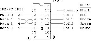
Commands to the stepper motor are easily given through the parallel port. The parallel port is a 25-pin communications port. The 1st pin signals when the computer is transmitting data. Pins 2-9 are data output pins (from computer to device), pins 10-17 are input pins (from device to computer), and pins 18-25 are grounding pins. Only pins 2-5 and possibly pin 25 are used for controlling the stepper motor.
Data is transfered through the parallel port in 1 byte (8 bit) increments (1 number at a time). Each of pins 2-9 represent 1 bit. An 8 bit communication system allows for the numbers 0-255 sent in binary. In binary, the possible numbers in each digit are 0 or 1 only.
0000 0001 = 1*2^0 = 1
0000 1001 = 1*2^3 + 1*2^0 = 9
0001 1001 = 1*2^4 + 1*2^3 + 1*2^0 = 25
1001 1001 = 1*2^7 + 1*2^3 + 1*2^0 = 153
The computer cannot actually read or communicate numbers. Instead, it uses a 5 volt signal and measures the voltage as "on" (5V) or "off" (0V), corresponding to "1" or "0" respectively. Pin 2 corresponds to the "one's" place (2^0, the far right digit in the binary numbers above), pin 3 corresponds to the "two's" place (2^1, the second digit from the right in the example above), and so on until pin 9, which corresponds to the "128's" place (2^7, the far left digit in the example above).
The KP4M4 stepper motor has 4 electromagnetic coils. Control of the stepper motor is very simple. When a voltage (and current) is applied to its electromagnetic coils, the permanent magnet on its rotor aligns with magnetic field. If the coils are magnetized successively in the correct order, the stepper motor is made to turn. The motor will turn 3.6 degrees per coil excitation, or 100 excitations per revolution. With the KP4M4 the correct sequence of coil excitations is simply 1, 2, 3, 4.
We need to send a series of numbers through the parallel port that correspond to turning on the motor coils in the correct sequence to get the rotor to spin. The simplest method is to excite 1 coil at a time, but if 2 coils are excited at the same time, we can increase torque from the motor as the magnetic fields will be stronger. In this case, we excite coils 1&4, 4&3, 3&2, and then 2&1. There is even a possible sequence of exciting 3 coils at a time in a similar fashion, but I found double coil excitation to be enough. The simplest way to do this is to send the following sequence of bytes:
0000 1001
0000 1100
0000 0110
0000 0011
These correspond to the numbers 9, 12, 6, and 3 (or in hexadecimal notation, 9, c, 6, 3). Since the leading 4 digits of each number are zero and those digits correspond to pins 6-9, we do not need to wire pins 6-9 to anything. When current from the 5V parallel port pin flows through the ULN2003 chip, the chip allows current to flow through the corresponding 12V (or 15V in my case) pin to the motor coils.
Windows XP makes it difficult to send signals through the parallel port (if you wish to use USB, you will have different challenges and I have no information on the subject). A driver (inpout32.dll) specifically designed to fool XP into thinking that your commands are native XP commands is required. Inpout32.dll needs only to be downloaded, unzipped, and copied to the Windows\system32\ folder to function correctly. The driver must be declared as a module in Visual Basic.net in the following manner:
Module InpOut32_declarations
Public Declare Function Inp Lib "inpout32.dll" Alias "Inp32" _
(ByVal PortAddress As Short) As Short
Public Declare Sub Out Lib "inpout32.dll" Alias "Out32" _
(ByVal PortAddress As Short, ByVal value As Short)
End Module
To send a number to the parallel port using inpout32, the number must be in hexadecimal (base 16) notation. The commands to send numbers through the parallel port (and hence activate the stepper motor) are:
Out(LPT, &H0S) 'Print '0' to D7-D0
a = &H9S
b = &HCS
c = &H6S
d = &H3S
For i = 0 To Steps
If i Mod 4 = 0 Then
Out(LPT, a)
ElseIf i Mod 4 = 1 Then
Out(LPT, b)
ElseIf i Mod 4 = 2 Then
Out(LPT, c)
ElseIf i Mod 4 = 3 Then
Out(LPT, d)
End If
j = DateTime.Now
Do Until Delay >= j.AddSeconds(dtime)
Delay = DateTime.Now
Loop
Next i
Out(LPT, &H0S)
I like to begin and end by turning off all of the motor coils (sending a "0" to the port) to be sure the motor rests between film advances. If the coils are in a constant state of excitement, the motor will wear out and burn out faster. In fact, the first thing my program does when it starts up is to send a "0" to the parallel port to be sure that random voltages in the port (all pin voltages are random until set to a specific value) do not keep the motor constantly excited. The bit of code above says that the computer will successively activate the coils of the motor until a certain number of steps has been achieved where 1 step = 3.6 degrees. Since my processor crunches through these numbers far faster than my port and motor can respond, I built a delay into the loop so that the code sends the number and holds it for a specified amount of time (0.01 seconds) in order to be sure that the motor and port respond to each step.
Go on to the VB Code
1. Interfacing with the scanning software to initiate scans
2. Controlling the stepper motor
Scanning Software Interface
I chose the simplest method for controlling the scanner; I simply pass key strokes to the scanning software (EpsonScan in professional mode) in order to initiate a scan. My program remains in a loop that searches for the expected file to appear in the expected folder on the hard drive during the scan. When the program registers that the file exists, it continues on with the processing of the file. The scanning software is started from my code, but it must be configured manually with the correct settings before the film can be scanned automatically. This means setting the destination folder for the scanned images and resetting the scan counter and image name. I use the image name "scan###" and I always scan in 24 bit BMP format (### indicates the scanning software counter).
In Visual Basic.net (Visual Studio 2005 was available to everyone for download from the Microsoft website), the scanning program is initially started from within my program and then the following code brings the scanning software to the foreground and passes keystrokes to initiate a scan:
AppActivate("EPSON Perfection 4870")
System.Windows.Forms.SendKeys.SendWait("{TAB}")
System.Windows.Forms.SendKeys.SendWait("s")
These commands perform the following actions (in order):
1. Make Epson Perfection 4870 the foreground application
2. Send the keystroke
In my code, the 1st and 3rd command are used every time a scan is initiated; however, the 2nd command is used only before the first scan. In addition, the code waits at least 0.5 seconds between sending consecutive commands as keystrokes (otherwise, the process executes the keystrokes faster than the program is able to respond resulting in missed commands).
Commands to the stepper motor are easily given through the parallel port. The parallel port is a 25-pin communications port. The 1st pin signals when the computer is transmitting data. Pins 2-9 are data output pins (from computer to device), pins 10-17 are input pins (from device to computer), and pins 18-25 are grounding pins. Only pins 2-5 and possibly pin 25 are used for controlling the stepper motor.
We need to send a series of numbers through the parallel port that correspond to turning on the motor coils in the correct sequence to get the rotor to spin. The simplest method is to excite 1 coil at a time, but if 2 coils are excited at the same time, we can increase torque from the motor as the magnetic fields will be stronger. In this case, we excite coils 1&4, 4&3, 3&2, and then 2&1. There is even a possible sequence of exciting 3 coils at a time in a similar fashion, but I found double coil excitation to be enough. The simplest way to do this is to send the following sequence of bytes:
0000 1001
0000 1100
0000 0110
0000 0011
These correspond to the numbers 9, 12, 6, and 3 (or in hexadecimal notation, 9, c, 6, 3). Since the leading 4 digits of each number are zero and those digits correspond to pins 6-9, we do not need to wire pins 6-9 to anything. When current from the 5V parallel port pin flows through the ULN2003 chip, the chip allows current to flow through the corresponding 12V (or 15V in my case) pin to the motor coils.
No comments:
Post a Comment