Thursday, October 25, 2007

Welcome

Welcome to my 8mm to DVD conversion story.

This blog walks you through the process I use to convert old family 8mm and super8 movies to DVD.

The information on this blog represents a personal investment of over 1000 hours of software and hardware development in addition to another 500 to 1000 hours of running experience. All told, I have scanned over 15,000 feet of film (about 3 miles). Please do not ask for a copy of my code (unless you would like to purchase it). I believe I have described the concepts and processes in sufficient detail for anyone with very basic skills in programing and mathematics to be able to reproduce my process and program on their own (I learned to program by creating this project).

If the information in this blog is helpful, if you have comments or questions, or if you have modifications or innovations of your own, I would like to hear about it. Please email Kyle at digireel@gmail.com.

None of what I present here would be possible without the help of the following individuals and their websites:
Richard Kinch Link
Todd Campbell
Jim Carroll Link
Jim Carroll's posted Java code was particularly helpful in developing my own version and some of the early steps of my process rely heavily on his code with some routines nearly identical to his. The concepts for the later processes are similar, though the approach and method are quite different.

Get Started

**NOTE** This blog is still under construction. Much of the content is missing. I will update and complete this blog as I have time. Thanks for your patience.
This blog represents my approach to a problem with many solutions. I make no promises inherent or implied with regard to any information contained here. By reading the content of this blog, you agree that under NO circumstances will I be held responsible for any damage to person or property as a result of any action taken by any individual in response to or because of any content of this blog.

Please also realize that I am not a programmer by profession and so I am sure my approach to programming is riddled with inefficiencies and bad practices - try not to hold it against me.

Background

Transferring 8mm and super8 movies to digital format can be done in many ways. I will mention 3 well established methods, but focus only on the last.

Method 1: Camcorder Telecine
In this method, the film is projected onto a screen and recorded by a camcorder. There are inherent problems with this method such as different frame rates in the two media. The 8mm or super8 film was recorded at 16 or 18 frames per second, respectively, but the camcorder will almost certainly record at 30 frames per second. This leads to flickering in the transfered movie. There are some projectors and camcorders that have been modified specifically to address this issue; however, there is also a loss of quality when the projected image is re-recorded. The loss of quality associated with this method makes this process unsuitable for archiving or preserving original film data.

Method 2: Camera Telecine
In this method, a modified projector has been set up to project or illuminate the original image of the film directly onto a high quality CCD imaging device (Megapixel digital camera without a lense). This method is very fast (up to several frames per second during transfer) and has the advantage of recording each individual frame with less loss of quality (and may even capture the grain of the film). The disadvantages are a high capital investment (starting at $2,495) for the combination projector/camera and the resulting images may be slightly clipped. This method may be suitable for archiving, but it may not capture the full resolution of the film. (I would love more information on this method if anyone has first hand experience - email Kyle at digireel [at] gmail [dot] com).


The only film tansfer company that I feel comfortable refering people to is Got Memories. Got Memories uses the camera telecine process described here and they are incredibly nice people to boot! I found them very willing to answer questions and work with customers on special projects.

Method 3: Flatbed Telecine
This is the method I use and believe to be the best as far as preservation of original film quality. In this method, a device is built to advance a section of the film across a flat bed film scanner. The scanner and the device are controlled by custom software which also identifies and crops each individual frame of the film. The main advantage of this method is greater control over the quality of the final product with scanners capable of 4800 dpi optical resolution and better (enough to capture the grain of the film). Some scanners are quite fast while others are very slow. Scanning the film at these high resolutions can capture the grain of the film (maximum detail possible on film). While nothing can replace films once lost, this method comes as close as possible to preserving all of the original data in a useful form. The main disadvantage of this method is the investment into developing a system (learning curve and actual construction) and the time required to scan the film. Materials will likely cost between $250 and $500 depending on how you choose to implement the system. On a modern Intel 2.4 GHz quad-core processor with 2GB of ram running WindowsXP, this system requires about 1 minute 54 seconds to process 22 frames. That amounts to about 6 hours/50 feet of film. Every 50 feet of film requires about 30 GB of hard drive space during scanning and capturing, so a 400 foot reel will require 240 GB of hard drive space and you will want extra space for editing and processing (probably at least 300 GB total space for a 400 foot reel). After processing, the final product can be 4.5 GB / 50 ft of film (or even less if you don't care about keeping the frame images) which easily fits on a DVD.

This blog focuses entirely on the Flatbed Telecine process.

A short background in 8mm and super8 film
8mm format film became available to the public around 1932, though it is rare to find films from earlier than about 1936 or 1937. Color and Black and White film were available almost from the beginning. I have some color films from 1938 that are still vibrant and true to the original hues while my color films from 1937 have almost completely lost their yellow dye (making them very red). Beginning in the 60s, the super8 format was developed and began to gain popularity. 8mm and super8 remained the standard formats until the 80's when camcorders became widely available. For a more detailed history, see Kodak's 8mm Film History.

Scan from a 1937 8mm home movie:


If you wish to see the 4800 dpi JPG file (513 KB), email me at digireel@gmail.com

The specs for 8mm are (image shows vertical orientation):
*NOTE: I did not develop this image or this spec table, but I cannot find the original source webpage. If you know it or find it, I would like to give proper credit to the creator.


(remember that 8mm is filmed on 16mm film stock and sliced in two, so this image shows 2 strips on a single film before it has been split)


DIMENSIONSmminches
Fw: Film width15.950.628
PCr: Picture Corner radius0.250.01
PEs: Picture Edge to Film Edge separation (Max)2.870.113
Ph: Picture height3.680.145
PPh: Picture Position horizontal7.540.297
PPv1: Picture Position vertical-10.810.032
PPv2: Picture position vertical-20.460.018
Pw: Picture width4.880.192
SEs: Sprocket hole to Picture Edge separation0.9020.0355
Sh: Sprocket hole height1.2700.05
Sr: Sprocket hole radius0.250.01
SSh: Sprocket hole Separation horizontal12.320.485
SSv: Sprocket hole Separation vertical (Long)3.8100.15
Sw: Sprocket hole width1.8290.0720


Scan from 1976 super8 home movie:

If you wish to see the 4800 dpi JPG file (576 KB), email me at digireel@gmail.com

The specs for super8 are (image shows vertical orientation):
*NOTE: I did not develop this image or this spec table, but I cannot find the original source webpage. If you know it or find it, I would like to give proper credit to the creator.


DIMENSIONSmmin
Fw: Film width7.9760.3140
PCr: Picture Corner radius0.130.005
PEs: Picture Edge to Film Edge separation (max)1.470.058
Ph: Picture Height4.140.163
PPh: Picture Position horizontal7.160.282
PPv: Picture Position vertical9.980.393
Pw: Picture width5.790.228
Sh: Sprocket hole height1.1430.045
Sr: Sprocket hole radius0.130.005
Ss: Sprocket hole separation (long)4.2340.1667
Sw: Sprocket hole width0.9140.036


From the scanned images above, we want to extract the individual frames and string them together into some kind of video format.

Single frame from 1937 8mm home movie:


Single frame from 1976 super8 home movie:


Short video clip of 1937 8mm home movie:


Short video clip of 1976 super8 home movie:


There is a bit of vertical shifting on the right side of the picture in the 1937 film. I believe this is due to curl in the film that I am not able to eliminate. The second video has a bit of vertical jumping and a repeated frame or two. These were some of the first films I transfered and I had not yet perfected all of my settings. Since these were transfered, I have fixed the vertical jumping and repeated frame issues, but the best I can do for curl is to sandwich the film between 2 panes of glass and try to keep it as flat as possible. Vertical jumping can be eliminated by scanning a smaller segment of film at a time. The videos above were taken from 32 frame scans. I now limit my scans to 25 frames and have no jumping at all. Since the scanning and processing scale linearly with the number of frames, no more time is required to process the film at 25 frames per scan than at 32 frames per scan; however, the scanner is performing a lot more scans at 25 than at 32.

See the Results section for the best examples of films.

I have organized my blog into sections to be a step by step guide to building your own flatbed telecine device. I start with building the hardware in the next section and finish with a detailed description of the computer code I wrote.

Go on to Hardware

Hardware

To perform flatbed telecine, you need:
Computer
Film Scanner
Custom Film Advancing Device

Computer
You will want a computer with a decent processor (P4 and above over 2.0 GHz) and you might consider a multi-core solution (depending on how patient you are - or aren't). You will definitely need a large hard drive (500 GB is nice, but you may want more if you plan on doing multiple projects at a time). The computer must have some kind of communication port. I prefer the ease of using a parallel port; however, someone more clever than I might be able to make use of the USB port for communicating with the Film Advancing Device.

Scanner

You need a good film scanner. I started my process using an Epson Perfection 4870 that I got re-manufactured for about $200 in 2006. In May of 2008, that scanner stopped functioning correctly, so I replaced it with an Epson Perfection V500 Photo scanner for $250. The only modifications to my system that I had to make were adjustments to the plywood base that positions my scanner and I had to make a new frame for holding the film in place on the scanner bed. If you choose to use a different scanner, you are on your own for figuring out keystrokes to control the scanning software. The scanner's optical resolution is very important. The purpose of scanning the film is to be able to preserve the original quality even though the film will continue to deteriorate. I recommend a resolution of 4800 dpi, but the V500 has the ability to scan at 6400 dpi optically.

Custom Film Advancing Device
Here is where the fun begins. The essential components for the device are:
1. Film Sprocket - $20
2. Stepper Motor - $20
3. Drive Chip (ULN2003) - $0.30
4. Computer interface port - $1
5. Gears - $12
6. Gearbox - $5
Total Cost - $60 (less if you know where to look)

Sprocket
Old sprockets are found in projectors and film editors. I found film editors to be the easiest, most useful and cheapest source (about $20 on ebay including shipping - cheaper if broken). Movie cameras are NOT a good source because unexposed film has different dimensions. Try to get a dual 8 sprocket that will do both 8mm and super8.

Stepper Motor
I suggest KP4M4-001 (found in very old disk drives). I happen to be a student at BYU and our electrical engineering department has a lab with lots of these motors, so they gave me a couple. I don't know where I would find them otherwise.

Drive Chip, Circuit Wiring, & Communication Port
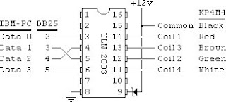
The ULN2003 is basically 7 logic gates in a single chip. The pins on each side are electrically isolated from each other. When current is passed through a pin on one side, it allows current to flow through the corresponding pin on the other side. In this way, you can use your computer's 5V I/O ports to control a 12V stepper motor. The power for the stepper motor can either come from your computer's 12V supply, or from an external DC power supply. I use 15V power supplies from Radio Shack. The image below is the wiring I use for my circuit and controlling chip for powering the KP4M4 motor. Note that there is a 15V Zener diode between the +12V and pin 9 of the ULN2003 to prevent electrical back flow to the computer as the motor winds down (a very good idea).


I used the Parallel Port because it seemed the easiest and most intuitive. Serial and USB may also be used, but I don't know how to do it. Only pins 2-5 of the parallel port are used in making the device (Pin 2 is the Data 0 Pin in the diagram above).

BEWARE: applying the wrong voltage or incorrectly wiring a circuit connected to your computer's communication ports will likely destroy your computer. If you are not comfortable with the risk of frying your computer, then you need to learn more before playing with this stuff. Anything you choose to do is at your own risk.

Gears & Structure

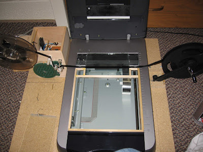
You are on your own for designing and building a gearbox. The two pictures below are different versions I made. One of the boxes is a jewelry box and the other is an inverted tissue box (both are unfinished hardwood) that I got at Joanne's Craft Store and can be found at most any craft store. The gears all came from a VEX Gear Kit that I bought at Radio Shack on clearance. I used plastic/metal cement to attach one of my sprockets to the gear in one of the designs. In the other, I used a Dremmel Tool and friction fit the sprocket onto the gear. The gear on the stepper motors are both friction set. I used 1/8 inch round hard wood dowels for axles. The gears rotate freely on the dowels, but the dowels are glued into place.


This last gearbox has an automated take-up reel. To turn the reel, I used the take-up arm from an old projector with the friction mechanism still intact. I used a 1/8 inch square metal dowel to connect the large gear on the outside of the box with a smaller gear inside the box. I had to reshape the gear inside the box to fit snugly with one of the other gears from the projector which turns the gears in the take-up arm. The take-up reel was a bit tricky to figure out, but sure beats finding 400 feet of film on the floor each morning.


I used screws to attach the gear box to a piece of plywood large enough to hold the scanner and gear box. I also built guides on the piece of plywood for the scanner so that it sits in exactly the same position relative to the gear box when I set up to do a scan.


I built a film guide that sits on the scanner bed to ensure that I get as little rotation and variation in film placement as possible. The guide consists of 2 pieces of plastic and a wooden frame. Turns out that thin CD jewel cases are just about perfect as film guides. Each of the plastic guides is actually two pieces of plastic glued together.

The first is just wide enough to hold the film (the film should move free when the guide is assembled, but the closer the fit, the better). The second piece is cut from the hinge side of the case and is long enough to position the film at the optimal distance from the top of the scanner to get a good scan. Together, the plastic and wood should fit snugly onto the bed of the scanner to prevent as much vertical movement as possible.


I noticed some Newton rings on very light sections of film as seen in these frames

Although light in these images, Newton rings show up on the video. They can be disipated with Anti-Newton ring glass as seen in this scan of the same frames from above:

Originally, I used 2 pieces of 4x6 inch anti-Newton ring glass to help eliminate the color rings. With the new scanner, I use 2 pieces of 2x6 inch anti-Newton ring glass. In both cases, a single pane of glass is 2mm thick. The glass had to be special ordered from here for $38/pane for the 4x6 or $20/pane for the 2x6 (just ask them for a quote on the size and type of glass you want). One piece of glass sits directly on the scanner bed ("fuzzy" side up) and the film goes over it. The other piece goes on top of the film ("fuzzy" side down) to sandwich the film between the coated sides of the glass. The weight of the glass also helps eliminate curl in the film. Both panes of glass should have completely smooth edges on all sides to avoid scratching the film. I have not noticed any scratching on the film as a result of the glass itself, but any hard particle sandwiched between the glass will scratch film moving past it.

Go on to Computer I/O

Computer I/O

This section is divided into 2 parts:
1. Interfacing with the scanning software to initiate scans
2. Controlling the stepper motor

Scanning Software Interface
I chose the simplest method for controlling the scanner; I simply pass key strokes to the scanning software (EpsonScan in professional mode) in order to initiate a scan. My program remains in a loop that searches for the expected file to appear in the expected folder on the hard drive during the scan. When the program registers that the file exists, it continues on with the processing of the file. The scanning software is started from my code, but it must be configured manually with the correct settings before the film can be scanned automatically. This means setting the destination folder for the scanned images and resetting the scan counter and image name. I use the image name "scan###" and I always scan in 24 bit BMP format (### indicates the scanning software counter).

In Visual Basic.net (Visual Studio 2005 was available to everyone for download from the Microsoft website), the scanning program is initially started from within my program and then the following code brings the scanning software to the foreground and passes keystrokes to initiate a scan:

AppActivate("EPSON Perfection 4870")
System.Windows.Forms.SendKeys.SendWait("{TAB}")
System.Windows.Forms.SendKeys.SendWait("s")

These commands perform the following actions (in order):
1. Make Epson Perfection 4870 the foreground application
2. Send the keystroke to the foreground application (prepares the scanning software to receive hotkey commands)
3. Send the keystroke "s" to the foreground application (starts a scan using the "s" hotkey)

If you are working on your computer (like typing this blog) at the same time that the program is running (as it is right now for me), you may get the timing just right so that when the program calls the scanning software to the foreground, you just happen to click on a link to edit your blog so that the blog comes to the foreground instead and you may find a random "s" in your text. The result is a poorly edited blog (sorry) and your program will continue to wait for the next scan which was never actually started. Continuing the program means that you have to push the "scan" button in the software. It should pick up automatically again from there. This is the hazard of using the key-stroke solution to the scanner interface problem.

In my code, the 1st and 3rd command are used every time a scan is initiated; however, the 2nd command is used only before the first scan. In addition, the code waits at least 0.5 seconds between sending consecutive commands as keystrokes (otherwise, the process executes the keystrokes faster than the program is able to respond resulting in missed commands).

After the 999th image is scanned, the Epsonscan software will not allow any further scanning until till the counter is reset to 001. As I do not want to overwrite any scans, I use the following code to change the scanned image name and image counter in the scanner settings:

If scans = 1000 Then
AppActivate("EPSON Perfection 4870")
Do Until DateTime.Now >= estart.AddSeconds(0.5)
Application.DoEvents()
Loop
System.Windows.Forms.SendKeys.SendWait("{TAB}")
System.Windows.Forms.SendKeys.SendWait(" ")
System.Windows.Forms.SendKeys.SendWait("{DOWN}")
System.Windows.Forms.SendKeys.SendWait("{ENTER}")
System.Windows.Forms.SendKeys.SendWait("{TAB}")
System.Windows.Forms.SendKeys.SendWait("{RIGHT}")
System.Windows.Forms.SendKeys.SendWait("1")
System.Windows.Forms.SendKeys.SendWait("{TAB}")
System.Windows.Forms.SendKeys.SendWait("1")
System.Windows.Forms.SendKeys.SendWait("{ENTER}")
scans += 1
End If

This code assumes that the last command given to the scanning software was "Scan." For this case in EpsonScan, "{TAB}" highlights the scanner settings button, " " (space) accesses the menu, "{DOWN}" selects the correct option, "{ENTER}" opens the change settings dialogue, "{TAB}" highlights the scanned image name, "{RIGHT}" moves the cursor to the far right of the name, "1" adds a 1 to the name, "{TAB}" highlights the image counter, "1" resets the counter to 001, and "{ENTER}" accepts the changes in the settings and closes the dialogue. In this way, the scanner automatically jumps from the image name "scan999.bmp" to "scan1001.bmp" and the scanning and processing continue as normal.

Stepper Motor Control
Commands to the stepper motor are easily given through the parallel port. The parallel port is a 25-pin communications port. The 1st pin signals when the computer is transmitting data. Pins 2-9 are data output pins (from computer to device), pins 10-17 are input pins (from device to computer), and pins 18-25 are grounding pins. Only pins 2-5 and possibly pin 25 are used for controlling the stepper motor.


Data is transfered through the parallel port in 1 byte (8 bit) increments (1 number at a time). Each of pins 2-9 represent 1 bit. An 8 bit communication system allows for the numbers 0-255 sent in binary. In binary, the possible numbers in each digit are 0 or 1 only.

0000 0001 = 1*2^0 = 1
0000 1001 = 1*2^3 + 1*2^0 = 9
0001 1001 = 1*2^4 + 1*2^3 + 1*2^0 = 25
1001 1001 = 1*2^7 + 1*2^3 + 1*2^0 = 153

The computer cannot actually read or communicate numbers. Instead, it uses a 5 volt signal and measures the voltage as "on" (5V) or "off" (0V), corresponding to "1" or "0" respectively. Pin 2 corresponds to the "one's" place (2^0, the far right digit in the binary numbers above), pin 3 corresponds to the "two's" place (2^1, the second digit from the right in the example above), and so on until pin 9, which corresponds to the "128's" place (2^7, the far left digit in the example above).

The KP4M4 stepper motor has 4 electromagnetic coils. Control of the stepper motor is very simple. When a voltage (and current) is applied to its electromagnetic coils, the permanent magnet on its rotor aligns with magnetic field. If the coils are magnetized successively in the correct order, the stepper motor is made to turn. The motor will turn 3.6 degrees per coil excitation, or 100 excitations per revolution. With the KP4M4 the correct sequence of coil excitations is simply 1, 2, 3, 4.


We need to send a series of numbers through the parallel port that correspond to turning on the motor coils in the correct sequence to get the rotor to spin. The simplest method is to excite 1 coil at a time, but if 2 coils are excited at the same time, we can increase torque from the motor as the magnetic fields will be stronger. In this case, we excite coils 1&4, 4&3, 3&2, and then 2&1. There is even a possible sequence of exciting 3 coils at a time in a similar fashion, but I found double coil excitation to be enough. The simplest way to do this is to send the following sequence of bytes:

0000 1001
0000 1100
0000 0110
0000 0011

These correspond to the numbers 9, 12, 6, and 3 (or in hexadecimal notation, 9, c, 6, 3). Since the leading 4 digits of each number are zero and those digits correspond to pins 6-9, we do not need to wire pins 6-9 to anything. When current from the 5V parallel port pin flows through the ULN2003 chip, the chip allows current to flow through the corresponding 12V (or 15V in my case) pin to the motor coils.

Windows XP makes it difficult to send signals through the parallel port (if you wish to use USB, you will have different challenges and I have no information on the subject). A driver (inpout32.dll) specifically designed to fool XP into thinking that your commands are native XP commands is required. Inpout32.dll needs only to be downloaded, unzipped, and copied to the Windows\system32\ folder to function correctly. The driver must be declared as a module in Visual Basic.net in the following manner:

Module InpOut32_declarations
Public Declare Function Inp Lib "inpout32.dll" Alias "Inp32" _
(ByVal PortAddress As Short) As Short
Public Declare Sub Out Lib "inpout32.dll" Alias "Out32" _
(ByVal PortAddress As Short, ByVal value As Short)
End Module

To send a number to the parallel port using inpout32, the number must be in hexadecimal (base 16) notation. The commands to send numbers through the parallel port (and hence activate the stepper motor) are:

Out(LPT, &H0S) 'Print '0' to D7-D0
a = &H9S
b = &HCS
c = &H6S
d = &H3S
For i = 0 To Steps
If i Mod 4 = 0 Then
Out(LPT, a)
ElseIf i Mod 4 = 1 Then
Out(LPT, b)
ElseIf i Mod 4 = 2 Then
Out(LPT, c)
ElseIf i Mod 4 = 3 Then
Out(LPT, d)
End If
j = DateTime.Now
Do Until Delay >= j.AddSeconds(dtime)
Delay = DateTime.Now
Loop
Next i
Out(LPT, &H0S)

I like to begin and end by turning off all of the motor coils (sending a "0" to the port) to be sure the motor rests between film advances. If the coils are in a constant state of excitement, the motor will wear out and burn out faster. In fact, the first thing my program does when it starts up is to send a "0" to the parallel port to be sure that random voltages in the port (all pin voltages are random until set to a specific value) do not keep the motor constantly excited. The bit of code above says that the computer will successively activate the coils of the motor until a certain number of steps has been achieved where 1 step = 3.6 degrees. Since my processor crunches through these numbers far faster than my port and motor can respond, I built a delay into the loop so that the code sends the number and holds it for a specified amount of time (0.01 seconds) in order to be sure that the motor and port respond to each step.

Go on to the VB Code

VB Code

The process of converting scanned film images to individual frames and avi movie files is not too complicated. The math and logic behind the methods are quite simple. Basically, you have to identify the sprockets, pick off the images, and compile them into a movie file. Identifying the sprockets sounds easy, but actually makes up about 90% of processing time and program code.

My program is built around a graphical user interface (GUI) to allow the user to be able to use the same code for many different operations including scanning and processing film, reprocessing a set of previously scanned film images, continuing a project that was interrupted before completion, or compiling a movie file from previously captured frames of a film.


The user may choose regular 8, super 8, frame rate, motor delay (time to wait between sending signals to the motor), automatic or manual calibration of sprocket size and position, and whether to create debugging images.

The main program simply keeps track of the number of scanned images and the number of frames that have been picked off and orchestrates the execution of the routines that advance film, initiate a scan, process the scan, and create the movie file.

In general, the program executes the following suedo-code:

Initialize parameters (depending on user choices)
Check to see if Scanning software is ready
- Not ready? Tell user and stop execution
Ask User for working directory
Create output directory
Number of scans = 0
Number of frames = 0
Main program loop
- Add 1 to total number of scans
- Check to see if there are 999 scanned images
- - Have 999 scanned images? Change file name & reset counter on Epsonscan software
- Predict filename of next scanned image
- Start Scan
- Scanning Loop
- - Check to see if expected file exists
- - - File Exists? Exit Loop
- End Scanning Loop
- Create grayscale Image
- Find edges
- Find Sprockets
- Pick off frames
- - Add frames picked off to total number of frames
- Advance Film
End Main Program Loop
Advance end of film through machine
Create movie file(s)
End Program

The next sections cover the algorithms for finding edges and sprockets in more detail.

A lot of time can be saved if the scanned images of the film are straight, consistent, and have little extra space above and below the film. In general, the top and bottom edge of the scanned film image should come as close to the film edge as possible. The edges of the film may even be cut off slightly, but cut too much off and the program will be unable to accurately find the sprockets or the frames.

In finding the sprockets, the full image is not needed. Only the top 1/3 - 1/2 of the image is required because once the position of the sprockets is known from the smaller, working image, the frames can be taken directly from the original image. Performing the sprocket finding algorithms on only the top third of the image reduces processing time by 75%!

Go on to Bitmap Tutorial

Bitmap Tutorial

Before you can understand how to manipulate images, you have to know how the computer sees them. For a bitmap image, the computer actually sees a HUGE series of numbers strung together in a single long list. Each number is 1 byte (8 bits, or 8 1's and 0's) between 0 and 255.

The first 40 bytes tell the computer how many bits per pixel, the number of pixels high and wide the image is, the physical dimensions of the original image (in inches), the compression format used (if any), etc.

The computer creates and stores images by defining a dot of color called a pixel. The images we see on a screen are created by mixing intensities of 3 colors for each pixel. The most common pixel format is 24 bit. 24 bit color allows for 256 different levels of intensity for each of the three colors that are combined to make every other color on the screen. As each combination of different levels of intensity results in a different color, 24 bit pixels can have up to 256 x 256 x 256 = 16,777,216 different colors. The three colors used by computers are blue, green, and red. To define a pixel, all that is needed is the relative intensity of the three colors. For example, the following sets of numbers define pixels of the corresponding color:

[0 0 0] = Black
[255 0 0] = Blue
[0 255 0] = Green
[0 0 255] = Red
[255 255 255] = White

When you and I think of a picture, we think of a 2 dimensional matrix of color dots, but the computer sees a very large list of numbers in only 1 dimension. The computer knows when one line of pixels stops and the next one starts based on the data in the first 40 bytes of the image. In order to correctly manipulate the image, the total number of pixels, the number of pixels in each row, and the number of rows must be known. In addition, the number of bytes in a row of the image must be an integer multiple of 4. If the number of pixels in a row does not give a number bytes that is an integer multiple of 4, the image file will have columns of "remainder" bytes at the end of the rows to meet this requirement. The remainder has a value from 0 to 3, is constant for each image, and represents the number of these "dummy" columns. The full length of the row in bytes including the remainder is called the "stride."

In Visual Basic, if the commands "Imports system.drawing.imaging" and "Imports system.runtime.interopservices" are included before any of the actual program code, then image as well as the important information can be retrieved as follows:

Dim bmd As BitmapData
Dim bm As Bitmap
Dim bmdat() as byte
bmd = bm.LockBits(New Rectangle(0, 0, bm.Width, bm.Height),
*****
Imaging.ImageLockMode.ReadWrite,
*****Imaging.PixelFormat.Format24bppRgb)

w = bmd.Width 'width of image in pixels
h = bmd.Height 'height of image in pixels
bmsize = w*h 'total size of image in pixels
ReDim bmdat(bmd.Stride * h - 1)
Marshal.Copy(bmd.Scan0, bmdat, 0, bmd.Stride * bmd.Height)
r = bmd.Stride - w * 3 'remainder in bytes

The code above copies the full image data in bytes into the 1 dimensional matrix "bmdat." Here, w is width in pixels, h is height in pixels, and r is the remainder in bytes.

Go on to Grayscale

Grayscale

The algorithms that find edges in the image require the image to be in grayscale.

In the Bitmap tutorial, example code was provided to capture the full pixel data of the original image. In finding the sprockets, only about the top 1/3 of the image will be used. The first step is to convert the top 1/3 of the full image data to grayscale data. This will not affect the original image, but has lots of advantages:

1. Simplicity: Each pixel can be represented by a single byte
2. Memory: Required storage space in memory will be less
3. Processor Time: Fewer numbers to crunch = less core time

I keep saying that we only need about the top 1/3 of the image, but to be exact, I take the frame width dimension (given in the background section), convert it from inches to pixels, and subtract it from the total height of the scanned image in pixels. The remaining image is all that is required until we are ready to pick off the actual frames.

Many algorithms for converting full color images to grayscale have been developed. I found one on the internet that works well, but I have lost the source. If you happen to know the source, please email me so that I may update this page (digireel@gmail.com). The algorithm I use is:

gray = 0.2 * blue + 0.5 * green + 0.3 * red

For 24 bit color, gray will end up as an integer from 0 to 255.
For example, a pixel with BGR color [125 200 50] would be:
0.2 * 125 + 0.5 * 200 + 0.3 * 50 = 140

When truncating the image and converting it to grayscale, the remainder must not be neglected (see the bitmap tutorial for discussion on the remainder). Forgetting to account for the remainder bytes at the end of each row may result in a final image that is slanted as much as 45 degrees to the left and that exhibits color shift. After the image is converted to grayscale, the remaining processes can be done without having to worry about the remainder until it is time to pick off the frames from the original image, or until a debugging image is to be created.

With the truncated image converted to grayscale, the data is ready for edge detection.

Go on to Canny Edge Detection

Canny Edge Detection

The process of finding edges in the image is accomplished by using the Canny Edge Detection method. This method is well documented on the internet and an excellent tutorial has been written by Bill Green.

The three steps to a Canny Edge Detection are:
1. Blur the image
2. Calculate image gradients
3. Create a hysteresis

Blurring
The image is blurred using a Gaussian Mask in order to filter out noise such as dust particles and faint lines (which we are not interested in). A normal probability function in 2 dimensions is used to calculate the Mask. The mask is applied to every pixel of the image for which the edges of the mask still fall on pixels (i.e. there will be some space on the edges that the mask will not be applied to). The following equation calculates the normal probability function used in creating the mask:

p = exp(-(x^2 + y^2)/(2 * sigma^2)) / (2 * Pi * sigma^2)

The mask is created in the following code:

win = 1 + 2 * Ceiling(3 * sigma)
center = Floor(win / 2)
ReDim gk(win - 1, win - 1)
xsum = 0
For i = 0 To win - 1
*****For j = 0 To win - 1
**********b = i - center
**********d = j - center
**********fx = Exp(-0.5 * (b ^ 2 + d ^ 2) / (sigma * sigma)) / _
************(sigma * sigma * 2 * pi)
**********gk(i, j) = fx
**********xsum = xsum + fx
*****Next j
Next i
For i = 0 To win - 1
*****For j = 0 To win - 1
**********gk(i, j) = gk(i, j) / xsum
*****Next j
Next i

Sigma is generally a user input. Good values of sigma range from 0.5 to 1.4. The larger the sigma, the greater the blurring, but the time required to apply the mask increases exponentially. I recommend a value of 1.0 as it seems to give adequate blurring and can be done in little time.

The mask is applied in the following code (note: idat() is the array containing the grayscale pixels values where each pixel is represented by a single byte):

For i = 0 To numberofpixels - 1
*****xdot = 0.0
*****xsum = 0.0
*****For cc = -center To center
**********For j = -center To center
***************If (((i + row) Mod row) + cc) >= 0 And _
*****************(((i + row) Mod row) + cc) _
*****************And (i + j * row) > 0 And (i + j * row)
********************xdot = xdot + idat(i + cc + j * row) * _
**********************gk(center + cc, center + j)
********************xsum = xsum + gk(center + cc, center + j)
***************End If
**********Next j
*****
Next cc
*****gdat(i) = (xdot / xsum) * boostblurfactor + 0.5
Next i
For i = 1 To numberofpixels - 1
*****idat(i) = gdat(i)
Next i

The boostblurfactor in the code above is just a constant for changing the amount of blur effect. I use a value of 0.9 because that is the value that was used in the source code I modeled my code from. The constant "row" is equal to the number of pixels in each row of the original image.

Gradients
To find the edges, it is not enough to know where the image is intensely dark or light, but rather to know where there is a very sudden change from dark to light (or light to dark). The gradient is a measure of the amount of change around each pixel. The following code calculates the gradients at each pixel (note that derx() and dery() are arrays that hold the values of the gradients in those directions and the magnitude() array holds the combined gradient for the pixel):

For i = 0 To numberofpixels - 1
*****'Compute x derivative
*****If i = 0 Or (i Mod row) = 0 Then
**********c = idat(i + 1)
**********d = idat(i)
**********delx(i) = c - d
*****ElseIf ((i + 1) Mod row) = 0 Then
**********c = idat(i)
**********d = idat(i - 1)
**********delx(i) = c - d
*****Else
**********c = idat(i + 1)
**********d = idat(i - 1)
**********delx(i) = c - d
*****End If

*****'Compute y derivative
*****If i <>**********c = idat(i + row)
**********d = idat(i)
**********dely(i) = c - d
*****ElseIf i > numberofpixels - row - 1 Then
**********c = idat(i)
**********d = idat(i - row)
**********dely(i) = c - d
*****Else
**********c = idat(i + row)
**********d = idat(i - row)
**********dely(i) = c - d
*****End If
*****If i Mod (467 * row) = 0 Then Application.DoEvents()
Next i

'Calculate the magnitude of the gradient
For i = 0 To numberofpixels - 1
*****sq1 = delx(i) * delx(i)
*****sq2 = dely(i) * dely(i)
*****magnitude(i) = 0.5 + Sqrt(sq1 + sq2)
Next i

After calculating the gradient, we need to suppress any pixel that is not a maximum. We will use three values to indicate pixel status as:
1. No Edge (0)
2. Possible Edge (128)
3. Definite Edge (255)

The pixels around the edges of the image will be set to No Edge. For the remaining pixels, a simple test shows whether the pixel in question is a possible edge or not, but the eight different directions from which the gradient may be coming create a complicated set of conditions for the test. The code is:

Dim i As Integer
Dim xperp, yperp, z1, z2, mag1, mag2 As Double

'Initialize parameters
ReDim idat(bmsize - 1) 'idat() is now the result array
noedge = 0
possedge = 128
edge = 255

'Zero the Result() Image Edges
For i = 0 To bmsize - 1
***** If i <> (bmsize - row - 1) Or (i Mod row) = 0 _
**********Or ((i + 1) Mod row) = 0 Or magnitude(i) = 0 Then
********** idat(i) = noedge
***** Else
********** xperp = -delx(i) / magnitude(i)
********** yperp = dely(i) / magnitude(i)
***** End If

***** If delx(i) >= 0 And dely(i) >= 0 And delx(i) >= dely(i) _
**********And i > row And i < (bmsize - row - 1) And (i Mod row) <> 0 _
**********And ((i + 1) Mod row) <> 0 Then
********** 'Left Point
********** z1 = magnitude(i - 1)
********** z2 = magnitude(i - row - 1)
********** mag1 = (magnitude(i) - z1) * xperp + (z2 - z1) * yperp

********** 'Right Point
********** z1 = magnitude(i + 1)
********** z2 = magnitude(i + row + 1)
********** mag2 = (magnitude(i) - z1) * xperp + (z2 - z1) * yperp
***** ElseIf delx(i) >= 0 And dely(i) >= 0 And delx(i) <> row _
**********And i < (bmsize - row - 1) And (i Mod row) <> 0 _
**********And ((i + 1) Mod row) <> 0 Then
********** 'Left Point
********** z1 = magnitude(i - row)
********** z2 = magnitude(i - row - 1)
********** mag1 = (z1 - z2) * xperp + (z1 - magnitude(i)) * yperp

**********'Right Point
********** z1 = magnitude(i + row)
********** z2 = magnitude(i + row + 1)
********** mag2 = (z1 - z2) * xperp + (z1 - magnitude(i)) * yperp
***** ElseIf delx(i) >= 0 And dely(i) <>= -dely(i) And i > row _
**********And i < (bmsize - row - 1) And (i Mod row) <> 0 _
**********And ((i + 1) Mod row) <> 0 Then
********** 'Left Point
********** z1 = magnitude(i - 1)
********** z2 = magnitude(i + row - 1)
********** mag1 = (magnitude(i) - z1) * xperp + (z1 - z2) * yperp

**********'Right Point
********** z1 = magnitude(i + 1)
********** z2 = magnitude(i - row + 1)
********** mag2 = (magnitude(i) - z1) * xperp + (z1 - z2) * yperp
***** ElseIf delx(i) >= 0 And dely(i) <> row And i < (bmsize - row - 1) _ **********And (i Mod row) <> 0 And ((i + 1) Mod row) <> 0 Then
**********'Left Point
**********z1 = magnitude(i + row)
**********z2 = magnitude(i + row - 1)
**********mag1 = (z1 - z2) * xperp + (magnitude(i) - z1) * yperp

********** 'Right Point
********** z1 = magnitude(i - row)
********** z2 = magnitude(i - row + 1)
********** mag2 = (z1 - z2) * xperp + (magnitude(i) - z1) * yperp
***** ElseIf delx(i) <>= 0 And -delx(i) >= dely(i) And i > row _
**********And i < (bmsize - row - 1) And (i Mod row) <> 0 _
**********And ((i + 1) Mod row) <> 0 Then
********** 'Left Point
********** z1 = magnitude(i + 1)
********** z2 = magnitude(i - row + 1)
********** mag1 = (z1 - magnitude(i)) * xperp + (z2 - z1) * yperp

**********'Right Point
********** z1 = magnitude(i - 1)
********** z2 = magnitude(i + row - 1)
********** mag2 = (z1 - magnitude(i)) * xperp + (z2 - z1) * yperp
***** ElseIf delx(i) <>= 0 And -delx(i) <> row And i < (bmsize - row - 1) **********And (i Mod row) <> 0 And ((i + 1) Mod row) <> 0 Then
********** 'Left Point
********** z1 = magnitude(i - row)
********** z2 = magnitude(i - row - 1)
********** mag1 = (z2 - z1) * xperp + (z1 - magnitude(i)) * yperp

********** 'Right Point
********** z1 = magnitude(i + row)
********** z2 = magnitude(i + row - 1)
********** mag2 = (z2 - z1) * xperp + (z1 - magnitude(i)) * yperp
***** ElseIf delx(i) <>= -dely(i) And i > row And i < (bmsize - row - 1) _ **********And (i Mod row) <> 0 And ((i + 1) Mod row) <> 0 Then
********** 'Left Point
********** z1 = magnitude(i + 1)
********** z2 = magnitude(i + row + 1)
********** mag1 = (z1 - magnitude(i)) * xperp + (z1 - z2) * yperp

********** 'Right Point
********** z1 = magnitude(i - 1)
********** z2 = magnitude(i - row - 1)
********** mag2 = (z1 - magnitude(i)) * xperp + (z1 - z2) * yperp
***** ElseIf i > row And i < (bmsize - row - 1) And (i Mod row) <> 0 _
**********And ((i + 1) Mod row) <> 0 Then
********** 'Left Point
********** z1 = magnitude(i + row)
********** z2 = magnitude(i + row + 1)
********** mag1 = (z2 - z1) * xperp + (magnitude(i) - z1) * yperp

**********'Right Point
********** z1 = magnitude(i - row)
********** z2 = magnitude(i - row - 1)
********** mag2 = (z2 - z1) * xperp + (magnitude(i) - z1) * yperp
***** End If

***** 'Now determine if the point is a maximum
*****If mag1 > 0.0 Or mag2 > 0.0 Then
********** idat(i) = noedge
***** ElseIf mag2 = 0.0 Then
********** idat(i) = noedge
***** Else
********** idat(i) = possedge
***** End If
***** If i Mod (467 * row) = 0 Then Application.DoEvents()
Next i

After filtering out all of the points that probably aren't edges, a hysteresis is created on the magnitude of the gradients for the remaining points. We choose a low and high threshold. If the magnitude of the gradient is lower than the low threshold, it cannot be an edge, but if it is above the high threshold, we assume it is an edge. Anything in between is considered a possible edge. As points are eliminated from the list of possible edge points, the image changes. We have to continue our comparison of gradient magnitudes and process of eliminating points until the image stops changing.

The code for generating the hysteresis and creating the edge data is given here:
Dim i, j, highc, hist(), edges, hight, lowt, tpos As Integer
Dim thigh As Single
Dim tlow As Single
Dim mmag As Short
Dim x() As Integer = {1, 1, 0, -1, -1, -1, 0, 1}
Dim y() As Integer = {0, 1, 1, 1, 0, -1, -1, -1}
Dim unchanged As Boolean

'Initialize parameters
ReDim hist(32768)
thigh = 0.9
tlow = 0.5
hist.Initialize()

For i = 0 To bmsize - 1
***** 'Initialize edges of image to noedge
***** If idat(i) = possedge Then idat(i) = possedge
**********Else idat(i) = noedge
*****If i <> bmsize - 1 - row Or ((i + row) Mod row) = 0
**********Or ((i + row + 1) Mod row) = 0 Then idat(i) = noedge

***** 'Creates the histogram of the magnitudes in the image
***** If idat(i) = possedge Then _
**********hist(magnitude(i)) = hist(magnitude(i)) + 1
Next i

'Calculate the number of pixels that pass the suppression
For i = 1 To 32767
***** If hist(i) <> 0 Then
********** mmag = i
********** edges = edges + hist(i)
***** End If
Next i

highc = edges * thigh + 0.5

I found this comment from Jim Carol's source code useful: Compute the high threshold value as the (100 * thigh) percentage point in the magnitude of the gradient histogram of all the pixels that passes non-maximal suppression. Then calculate the low threshold as a fraction of the computed high threshold value. John Canny said in his paper "A Computational Approach to Edge Detection" that "The ratio of the high to low threshold in the implementation is in the range two or three to one." That means that in terms of this implementation, we should choose tlow ~= 0.5 or 0.33333.

i = 1
edges = hist(1)
Do While i < (mmag - 1) And edges <>
*****i = i + 1
*****edges = edges + hist(i)
Loop
hight = i
lowt = hight * tlow + 0.5

'Looks for pixels above the hight to locate edges we will need to run over the entire image until it stops changing. In this first step we seed the image with everything that is clearly an edge by being above the high threshold.

For i = 0 To bmsize - 1
*****If idat(i) = possedge And magnitude(i) >= hight Then idat(i) = edge
Next i

'run over image until it stops changing
unchanged = False
Do While unchanged = False
***** unchanged = True
*****For j = 0 To bmsize - 1
**********If idat(j) = edge Then
***************For i = 0 To 7
******************** tpos = j - y(i) * row + x(i)
********************If idat(tpos) = possedge _
*************************And magnitude(tpos) > lowt Then
************************* unchanged = False
******************** ***** idat(tpos) = edge
********************End If
***************Next i
**********End If
*****Next j
Loop

'Set any remaining possible edges to non-edge
For i = 0 To bmsize - 1
*****If idat(i) <> edge Then idat(i) = noedge
Next i

'idat() now has the edge data stored to it

An edge image can be exported to bmp format by assigning the value of each point in idat() to all three of the color values for each pixel of a bitmap image with the original dimensions as explained in the bitmap tutorial. Edge images have exactly 2 colors: black and white. I will occasionally use an edge image for troubleshooting purposes.

With the edge image, it is now possible to look for shapes in our bitmap. We will use this ability to find the sprockets holes in the film. Once the sprockets are known, the frames are easily picked off.

Go on to Sprockets